How to make your own
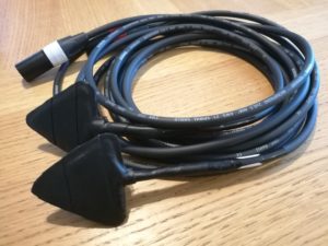
Triangular Balanced Contact Microphone
By Victor Engström
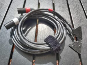
Balanced contact microphone?
Unbalanced contact microphones sound very dull/tinny without an impedance transformer.
This is a DIY alternative without needing an impedance converter.
If you don´t feel like building it yourself, you can go buy high quality contact microphones from Jez Riley French (and make sure to get some impedance converters too).
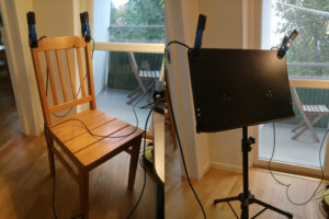
Here is an audio example comparing my balanced triangular contact microphone to a unbalanced circular contact microphone plugged in straight into my soundcard.
Triangular contact microphones?
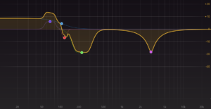
From my experiments I have found out that triangular shaped piezo discs have a flatter response curve with less pronounced ringing in the mid and picks up lower frequencies.
Here is a frequency difference between the balanced contact microphone matching to the triangular balanced contact microphone. Notice it has less ringing in the mid (3kHz), less mud (200Hz) and more bass.
Materials you need for making 2 mono microphones:
4 piezo elements
The bigger the better, I bought the biggest piezo element which I could find.
KEPO FT-50T-3.0A1-481 Piezo Ceramic element
4 meters of balanced microphone cable
Get lavalier microphone cable if you can. Because its really thin it transmits less vibrations through the cable (handling noise).
Sommer Cable Cicada SO-D14 (2.6mm diameter)
2 male XLR plugs
Epoxy adhesive or silicone paste
Epoxy creates a strong bond and gets hard which is better for transmitting the vibrations to both discs.
Silicone is easier to manage but is softer and might make the sound duller.
For the microphones I show here I have used hot glue, which is messy and hot (burns your fingers) so I would recommend either epoxy or silicone. Also it does not withstand heat that well (if you wanna record some hot sounds).
Liquid electrical tape
For covering the finished product, it’s a nice touch for looks and also for electrical insulation so you don’t fry your recorder if you touch something charged with electricity. Also used for covering the solder joints and wires without affecting the sound.
Masking tape
Soldering iron
Solder
Nippers
Tin snips
How to build
Soldering the XLR connector
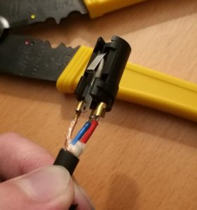
Cut the microphone cable into two equal lengths and solder your XLR connector so you get that out of the way. Don’t forget to put on the end caps first before you solder it. Next time I’ll use thin lavalier microphone cable instead of the regular thick microphone cable.
- Solder ground/shield to pin 1.
- Solder positive/hot to pin 2 (red).
- Solder negative/cold to pin 3 (blue).
Cutting the piezo elements
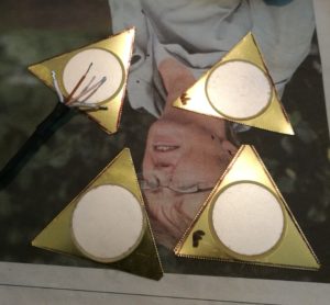
Cut the piezo elements into triangles with tin snips. I’ve kept track on which is the “front” so that I can connect the blue wire to that one so that both microphones are in phase.
Preparing the microphone cable
Divide the shield in two strands (one for each pizeo disc) and insulate the shielding so it does not accidentally touch any part of the ceramic white disc. This can be done by painting the exposed shielding strands with liquid electrical tape.
(I’ve tried heat-shrink tubing and the problem is that it does squeak if you bend them which can ruin the recording. Also in this photo I used vulcanized tape but liquid electrical tape is better).
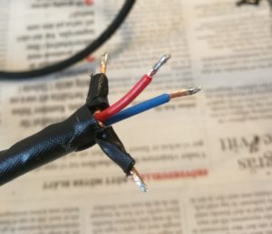
Prep the microphone cable for soldering by pre-tinning them.
Soldering the piezo element
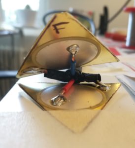
Then solder the blue wire to the “front” the red to the “back” and the shielding to the metal diaphragm.
Taping the sides
Use masking tape to cover the outside of the piezo element and the cable from getting any epoxy (or silicone) on them. This is a photo from the later build of my fine filler contact microphones.
Filling it
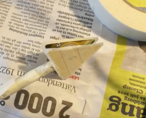
Then put epoxy (or silicone) in between the discs, press them together and let it cure. Make sure that the two sides do not touch. If you want you can paint the joints with liquid electrical tape.
I have not tried this with epoxy yet, but If you do, you’d need some kind of mold to cast it in because it’s quite runny.
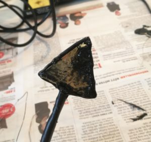
Cleaning it up
Here I have removed most of the hot glue residue from the outside with a knife. Next time I’ll use epoxy instead (and also tape the sides with masking tape).
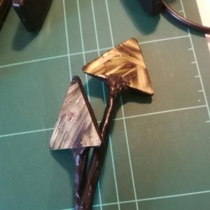
Painting it
Then paint the microphones with liquid electrical tape and mark the “front side” with some visual marking.

Done! 🙂
Fine filler test
I also tried making a pair of fine filler (two component plastic which hardens slowly), but which (as I later found out) is not as adhesive enough.
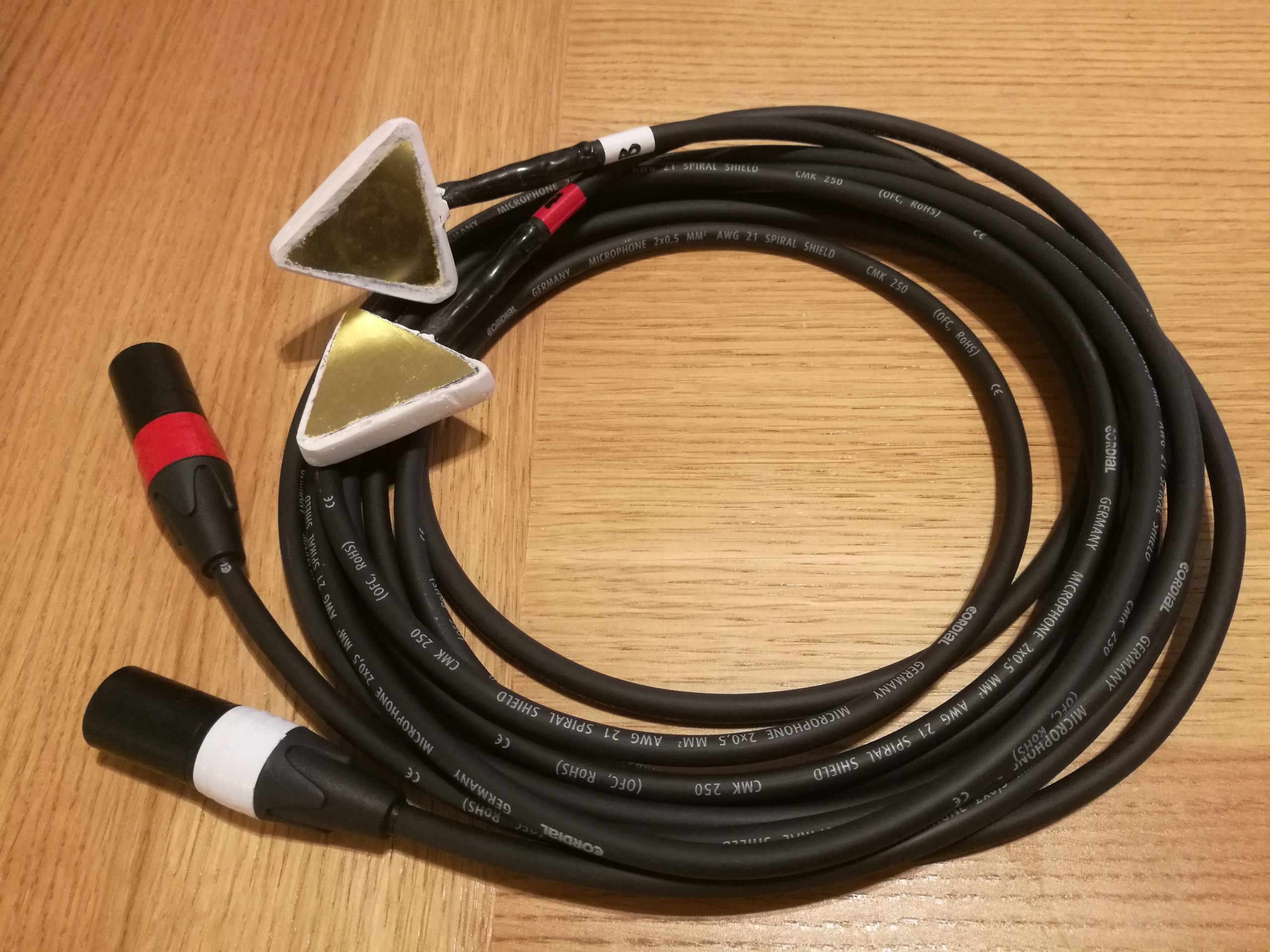
Dont use adhesive!
While I waited for the delivery, I tried them out by clamping them and putting adhesive on, but the adhesive was so sticky it broke one of them when I tried to remove it.
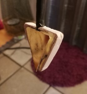
How to fasten
From what I’ve read later I have heard that fastening the microphones with just clamps/clips and electrical tape. I think the liquid electrical tape I put on later is enough of a “soft layer” so it’ll stick better to surfaces with just a clamp/clip and not “jar”.
Vulcanized rubber test
I also did one with vulcanized rubber on, but it damped the sound too much for my taste. The liquid electrical tape is the best final coating layer I tried.
Hope you all can learn a bit from my trials and make some great microphones yourselves!
Happy recording!
Victor Engström